Network Technologies Inc, Innovators in KVM Solutions

PS/2 Keyboard Mouse Protocols

Auxiliary Device System Timings

Home | Shop | About Us | Contact Us

PS/2 Keyboard & Mouse Protocols

Auxiliary Device and System Timings


Data transmissions to and from the auxiliary device connector consist of an 11-bit data stream sent serially over the 'data' line. The following table shows the function of each bit. The parity bit is either 1 or 0, and the 8 data bits, plus the parity bit, always have an odd number of 1's.    
BIT FUNCTION
11 Stop bit (always 1)
10 Party Bit (odd partly)
9 Data Bit 7 (most-significant)
8 Data Bit 6
7 Data Bit 5
6 Data Bit 4
5 Data Bit 3 (most-significant)
4 Data Bit 2
3 Data Bit 1
2 Data Bit 0 (least-significant)
1 Start Bit (always 0)

System Receiving Data

Timings for data received from the auxiliary device

system receiving data
The following describes the typical sequence of events when the system is receiving data from the auxiliary device.

1. The auxiliary device checks the 'clock' line. If the line is inactive, output from the device is not allowed.

2. The auxiliary device checks the 'data' line. If the line is inactive, the controller receives data from the system.

3. The auxiliary device checks the 'clock' line during the transmission at intervals not exceeding 100 microseconds. If the device finds the system holding the 'clock' line inactive, the transmission is terminated. The system can terminate transmission anytime during the first 10 clock cycles.

4. A final check for terminated transmission is performed at least 5 microseconds after the 10th clock.

5. The system can hold the 'clock' signal inactive to inhibit the next transmission.

6. The system can set the 'data' line inactive if it has a byte to transmit to the device. The 'data' line is set inactive when the start bit (always 0) is placed on the 'data' line.

7. The system raises the 'clock' line to allow the next transmission.
   
  TIMING PARAMETER Min/Max
T1 Time from DATA transition to falling edge of CLK 5/25 us
T2 Time from rising edge of CLK to DATA transition 5/T4 - 5 us
T3 Duration of CLK inactive 30/50 us
T4 Duration of CLK active 30/50 us
T5 Time to auxiliary device inhibit after clock 11 to ensure the auxiliary device does not start another transmission >0/50 us

System Sending Data

Timings for data sent to the auxiliary device

system sending data
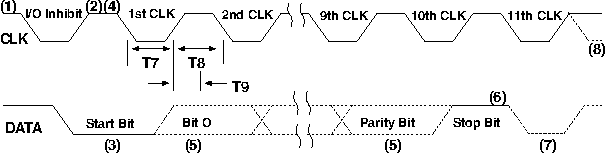
The following describes the typical sequence of events when the system is sending data from the auxiliary device.

1. The system checks for an auxiliary device transmission in process. If a transmission is in process and beyond the 10th clock, the system must receive the data.

2. The auxiliary device checks the 'clock' line. If the line is inactive, an I/O operation is not allowed.

3. The auxiliary device checks the 'data' line. If the line is inactive, the system has data to transmit. The 'data' line is set inactive when the start bit (always 0) is placed on the 'data' line.

4. The auxiliary device sets the 'clock' line inactive. The system then places the first bit on the 'data' line. Each time the auxiliary device sets the 'clock' line inactive, the system places the next bit on the 'data' line until all bits are transmitted.

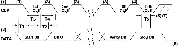
5. The auxiliary device samples the 'data' line for each bit while the 'clock' line is active. Data must be stable within 1 microsecond after the rising edge of the 'clock' line.

6. The auxiliary device checks for a positive-level stop bit after the 10th clock. If the 'data' line is inactive, the auxiliary device continues to clock until the 'data' line becomes active. Then it clocks the line-control bit and , at the next opportunity, sends a Resend command to the system.

7. The auxiliary device pulls the 'data' line inactive, producing the line-control bit.

8. The system can pull the 'clock' line inactive, inhibiting the auxiliary device.
   
  TIMING PARAMETER Min/Max
T7 Duration of CLK inactive 30/50 us
T8 Duration of CLK active 30/50 us
T9 Time from inactive to active CLK transition, used to time when the auxiliary device samples DATA 30/50 us
T4 Duration of CLK inactive 30/50 us
T5 Time to auxiliary device inhibit after clock 11 to ensure the auxiliary device does not start another transmission >0/50 us

Return to the Technical Reference Index

International Distributors
International
Distributors


Order now, call
800-RGB-TECH
800-742-8324

Contact NTI
NTI logo
1275 Danner Drive
Aurora, OH 44202
Tel: 330-562-7070
Fax: 330-562-1999
Free catalogFREE
CATALOG