USB Keyboard Mouse ProtocolsAuxiliary Device System Timings |
Home | Shop | About Us | Contact Us | |
USB KEYBOARD & MOUSE PROTOCOLS
Auxiliary Device and System Timings
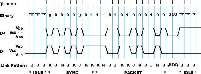
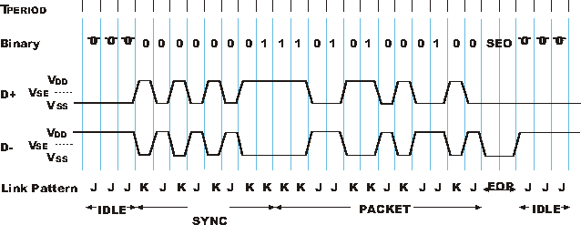
For both high and low speed links, a Differential 1 denotes whenever the D+ signal line voltage is 200 mv greater than the D- signal voltage. Similarly, a Differential 0 denotes whenever the D+ signal voltage is 200 mV less than the D- signal voltage. The states of "1" and "0" are defined when the Differential 1 and Differential 0 are driven onto the signals during the idle periods between packet transmissions. In Figures A and B, this is shown as "1" and "0" in the Binary row of the drawing. The state of "1" and "0" represent a constant Differential 1 and 0. When the transmission of a packet starts, the D+ and D- signals will change polarity during the synchronization and data portions of the packet transmission. The differential value of the D+ and D- signals interchange dependent on the information transmitted and the non-return to zero inverted protocol (NRZI). The information is transmitted in both high and low speed links is the same as in both figures A and B. As defined in the binary row of the figures, the synchronization portion of the information is 110101000100. The link transmission of the synchronization and data uses a differential pattern on the D+ and D- signals. Figures A and B show that the polarity of the D+ and D- signals during the packet transmission is opposite between high and low speed links. The convention for USB specifications is to use "J" and "K" states for protocol convenience that is independent of the link speed. The value of the J and K states for the high speed link is opposite of the values for the low speed link. Thus, as reflected in Figures A and B, the sequence of J and K states are identical for the two link speeds across the idle periods and the packet transmission. |
FIGURE A: HIGH SPEED LINK

FIGURE B: LOW SPEED LINK


FIGURE B: LOW SPEED LINK

SEO is defined when both D+ and D- signals are less than Vse. The SEO is part of the end of packet (EOP) protocol and also defines the rest of the link. The D+ and D- signals are also used to define whether a device is connected to a link and the speed of that link. |
Table C: Signal Definitions for D+ and D-
| ITEM | D+ (1) | D- (1) | Absolute Value of (D+)-(D-) | ||
| "0" for D+ | <Vse (min) | N/A | N/A | ||
| "0" for D- | N/A | <Vse (min) | N/A | ||
| "1" for D+ | >Vse (max) | N/A | N/A | ||
| "1" for D- | N/A | >Vse (max) | N/A | ||
| Differential 0 HIGH Speed Link | <Vse (min) | & | >Vse (max) | & | >200millivolts |
| Differential 1 HIGH Speed Link | >Vse (max) | & | <Vse (min) | & | >200millivolts |
| Differential 0 LOW Speed Link | <Vse (min) | & | >Vse (max) | & | >200millivolts |
| Differential 1 LOW Speed Link | >Vse (max) | & | <Vse (min) | & | >200millivolts |
| J State HIGH Speed Link | >Vse (max) | & | <Vse (min) | N/A | |
| J State LOW Speed Link | >Vse (min) | & | >Vse (max) | N/A | |
| J State HIGH Speed Link | differential >Vse (max) | & | differential <Vse (min) | & | differential >200millivolt |
| J State LOW Speed Link | differential <Vse (min) | & | differential >Vse (max) | & | differential >200millivolt |
| K State HIGH Speed Link | differential <Vse (max) | & | differential >Vse (max) | & | differential <200millivolt |
| K State LOW Speed Link | differential <Vse (max) | & | differential <Vse (min) | & | differential <200millivolt |
| Single Ended Zero (SEO) | <Vse (min) | & | <Vse (min) | N/A | |
| Disconnected | <Vse (max) for <=2.5 usec | & | <Vse (max) for <=2.5 usec | N/A | |
| Connected HIGH Speed Link | >Vse (max) for <=2.5 usec | & | <Vse (min) for <=2.5 usec | N/A | |
| Connected Low Speed Link | <Vse (min) for <=2.5 usec | & | <Vse (max) for <=2.5 usec | N/A |

 FREE
FREE